This graph shows which files directly or indirectly include this file:
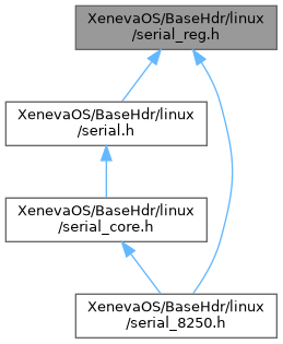
Go to the source code of this file.
Macros | |
| #define | UART_RX 0 /* In: Receive buffer */ |
| #define | UART_TX 0 /* Out: Transmit buffer */ |
| #define | UART_IER 1 /* Out: Interrupt Enable Register */ |
| #define | UART_IER_MSI 0x08 /* Enable Modem status interrupt */ |
| #define | UART_IER_RLSI 0x04 /* Enable receiver line status interrupt */ |
| #define | UART_IER_THRI 0x02 /* Enable Transmitter holding register int. */ |
| #define | UART_IER_RDI 0x01 /* Enable receiver data interrupt */ |
| #define | UART_IERX_SLEEP 0x10 /* Enable sleep mode */ |
| #define | UART_IIR 2 /* In: Interrupt ID Register */ |
| #define | UART_IIR_NO_INT 0x01 /* No interrupts pending */ |
| #define | UART_IIR_ID 0x0e /* Mask for the interrupt ID */ |
| #define | UART_IIR_MSI 0x00 /* Modem status interrupt */ |
| #define | UART_IIR_THRI 0x02 /* Transmitter holding register empty */ |
| #define | UART_IIR_RDI 0x04 /* Receiver data interrupt */ |
| #define | UART_IIR_RLSI 0x06 /* Receiver line status interrupt */ |
| #define | UART_IIR_BUSY 0x07 /* DesignWare APB Busy Detect */ |
| #define | UART_IIR_RX_TIMEOUT 0x0c /* OMAP RX Timeout interrupt */ |
| #define | UART_IIR_XOFF 0x10 /* OMAP XOFF/Special Character */ |
| #define | UART_IIR_CTS_RTS_DSR 0x20 /* OMAP CTS/RTS/DSR Change */ |
| #define | UART_IIR_64BYTE_FIFO 0x20 /* 16750 64 bytes FIFO */ |
| #define | UART_IIR_FIFO_ENABLED 0xc0 /* FIFOs enabled / port type identification */ |
| #define | UART_IIR_FIFO_ENABLED_8250 0x00 /* 8250: no FIFO */ |
| #define | UART_IIR_FIFO_ENABLED_16550 0x80 /* 16550: (broken/unusable) FIFO */ |
| #define | UART_IIR_FIFO_ENABLED_16550A 0xc0 /* 16550A: FIFO enabled */ |
| #define | UART_IIR_FIFO_ENABLED_16750 0xe0 /* 16750: 64 bytes FIFO enabled */ |
| #define | UART_FCR 2 /* Out: FIFO Control Register */ |
| #define | UART_FCR_ENABLE_FIFO 0x01 /* Enable the FIFO */ |
| #define | UART_FCR_CLEAR_RCVR 0x02 /* Clear the RCVR FIFO */ |
| #define | UART_FCR_CLEAR_XMIT 0x04 /* Clear the XMIT FIFO */ |
| #define | UART_FCR_DMA_SELECT 0x08 /* For DMA applications */ |
| #define | UART_FCR_R_TRIG_00 0x00 |
| #define | UART_FCR_R_TRIG_01 0x40 |
| #define | UART_FCR_R_TRIG_10 0x80 |
| #define | UART_FCR_R_TRIG_11 0xc0 |
| #define | UART_FCR_T_TRIG_00 0x00 |
| #define | UART_FCR_T_TRIG_01 0x10 |
| #define | UART_FCR_T_TRIG_10 0x20 |
| #define | UART_FCR_T_TRIG_11 0x30 |
| #define | UART_FCR_TRIGGER_MASK 0xC0 /* Mask for the FIFO trigger range */ |
| #define | UART_FCR_TRIGGER_1 0x00 /* Mask for trigger set at 1 */ |
| #define | UART_FCR_TRIGGER_4 0x40 /* Mask for trigger set at 4 */ |
| #define | UART_FCR_TRIGGER_8 0x80 /* Mask for trigger set at 8 */ |
| #define | UART_FCR_TRIGGER_14 0xC0 /* Mask for trigger set at 14 */ |
| #define | UART_FCR6_R_TRIGGER_8 0x00 /* Mask for receive trigger set at 1 */ |
| #define | UART_FCR6_R_TRIGGER_16 0x40 /* Mask for receive trigger set at 4 */ |
| #define | UART_FCR6_R_TRIGGER_24 0x80 /* Mask for receive trigger set at 8 */ |
| #define | UART_FCR6_R_TRIGGER_28 0xC0 /* Mask for receive trigger set at 14 */ |
| #define | UART_FCR6_T_TRIGGER_16 0x00 /* Mask for transmit trigger set at 16 */ |
| #define | UART_FCR6_T_TRIGGER_8 0x10 /* Mask for transmit trigger set at 8 */ |
| #define | UART_FCR6_T_TRIGGER_24 0x20 /* Mask for transmit trigger set at 24 */ |
| #define | UART_FCR6_T_TRIGGER_30 0x30 /* Mask for transmit trigger set at 30 */ |
| #define | UART_FCR7_64BYTE |
| #define | UART_FCR_R_TRIG_SHIFT 6 |
| #define | UART_FCR_R_TRIG_BITS(x) (((x) & UART_FCR_TRIGGER_MASK) >> UART_FCR_R_TRIG_SHIFT) |
| #define | UART_FCR_R_TRIG_MAX_STATE 4 |
| #define | UART_LCR 3 /* Out: Line Control Register */ |
| #define | UART_LCR_DLAB 0x80 /* Divisor latch access bit */ |
| #define | UART_LCR_SBC 0x40 /* Set break control */ |
| #define | UART_LCR_SPAR 0x20 /* Stick parity (?) */ |
| #define | UART_LCR_EPAR 0x10 /* Even parity select */ |
| #define | UART_LCR_PARITY 0x08 /* Parity Enable */ |
| #define | UART_LCR_STOP 0x04 /* Stop bits: 0=1 bit, 1=2 bits */ |
| #define | UART_LCR_WLEN5 0x00 /* Wordlength: 5 bits */ |
| #define | UART_LCR_WLEN6 0x01 /* Wordlength: 6 bits */ |
| #define | UART_LCR_WLEN7 0x02 /* Wordlength: 7 bits */ |
| #define | UART_LCR_WLEN8 0x03 /* Wordlength: 8 bits */ |
| #define | UART_LCR_CONF_MODE_A UART_LCR_DLAB /* Configutation mode A */ |
| #define | UART_LCR_CONF_MODE_B 0xBF /* Configutation mode B */ |
| #define | UART_MCR 4 /* Out: Modem Control Register */ |
| #define | UART_MCR_CLKSEL 0x80 /* Divide clock by 4 (TI16C752, EFR[4]=1) */ |
| #define | UART_MCR_TCRTLR 0x40 /* Access TCR/TLR (TI16C752, EFR[4]=1) */ |
| #define | UART_MCR_XONANY 0x20 /* Enable Xon Any (TI16C752, EFR[4]=1) */ |
| #define | UART_MCR_AFE 0x20 /* Enable auto-RTS/CTS (TI16C550C/TI16C750) */ |
| #define | UART_MCR_LOOP 0x10 /* Enable loopback test mode */ |
| #define | UART_MCR_OUT2 0x08 /* Out2 complement */ |
| #define | UART_MCR_OUT1 0x04 /* Out1 complement */ |
| #define | UART_MCR_RTS 0x02 /* RTS complement */ |
| #define | UART_MCR_DTR 0x01 /* DTR complement */ |
| #define | UART_LSR 5 /* In: Line Status Register */ |
| #define | UART_LSR_FIFOE 0x80 /* Fifo error */ |
| #define | UART_LSR_TEMT 0x40 /* Transmitter empty */ |
| #define | UART_LSR_THRE 0x20 /* Transmit-hold-register empty */ |
| #define | UART_LSR_BI 0x10 /* Break interrupt indicator */ |
| #define | UART_LSR_FE 0x08 /* Frame error indicator */ |
| #define | UART_LSR_PE 0x04 /* Parity error indicator */ |
| #define | UART_LSR_OE 0x02 /* Overrun error indicator */ |
| #define | UART_LSR_DR 0x01 /* Receiver data ready */ |
| #define | UART_LSR_BRK_ERROR_BITS (UART_LSR_BI|UART_LSR_FE|UART_LSR_PE|UART_LSR_OE) |
| #define | UART_MSR 6 /* In: Modem Status Register */ |
| #define | UART_MSR_DCD 0x80 /* Data Carrier Detect */ |
| #define | UART_MSR_RI 0x40 /* Ring Indicator */ |
| #define | UART_MSR_DSR 0x20 /* Data Set Ready */ |
| #define | UART_MSR_CTS 0x10 /* Clear to Send */ |
| #define | UART_MSR_DDCD 0x08 /* Delta DCD */ |
| #define | UART_MSR_TERI 0x04 /* Trailing edge ring indicator */ |
| #define | UART_MSR_DDSR 0x02 /* Delta DSR */ |
| #define | UART_MSR_DCTS 0x01 /* Delta CTS */ |
| #define | UART_MSR_ANY_DELTA (UART_MSR_DDCD|UART_MSR_TERI|UART_MSR_DDSR|UART_MSR_DCTS) |
| #define | UART_SCR 7 /* I/O: Scratch Register */ |
| #define | UART_DLL 0 /* Out: Divisor Latch Low */ |
| #define | UART_DLM 1 /* Out: Divisor Latch High */ |
| #define | UART_DIV_MAX 0xFFFF /* Max divisor value */ |
| #define | UART_EFR 2 /* I/O: Extended Features Register */ |
| #define | UART_XR_EFR 9 /* I/O: Extended Features Register (XR17D15x) */ |
| #define | UART_EFR_CTS 0x80 /* CTS flow control */ |
| #define | UART_EFR_RTS 0x40 /* RTS flow control */ |
| #define | UART_EFR_SCD 0x20 /* Special character detect */ |
| #define | UART_EFR_ECB 0x10 /* Enhanced control bit */ |
| #define | UART_XON1 4 /* I/O: Xon character 1 */ |
| #define | UART_XON2 5 /* I/O: Xon character 2 */ |
| #define | UART_XOFF1 6 /* I/O: Xoff character 1 */ |
| #define | UART_XOFF2 7 /* I/O: Xoff character 2 */ |
| #define | UART_TI752_TCR 6 /* I/O: transmission control register */ |
| #define | UART_TI752_TLR 7 /* I/O: trigger level register */ |
| #define | UART_TRG |
| #define | UART_TRG_1 0x01 |
| #define | UART_TRG_4 0x04 |
| #define | UART_TRG_8 0x08 |
| #define | UART_TRG_16 0x10 |
| #define | UART_TRG_32 0x20 |
| #define | UART_TRG_64 0x40 |
| #define | UART_TRG_96 0x60 |
| #define | UART_TRG_120 0x78 |
| #define | UART_TRG_128 0x80 |
| #define | UART_FCTR 1 /* Feature Control Register */ |
| #define | UART_FCTR_RTS_NODELAY 0x00 /* RTS flow control delay */ |
| #define | UART_FCTR_RTS_4DELAY 0x01 |
| #define | UART_FCTR_RTS_6DELAY 0x02 |
| #define | UART_FCTR_RTS_8DELAY 0x03 |
| #define | UART_FCTR_IRDA 0x04 /* IrDa data encode select */ |
| #define | UART_FCTR_TX_INT 0x08 /* Tx interrupt type select */ |
| #define | UART_FCTR_TRGA 0x00 /* Tx/Rx 550 trigger table select */ |
| #define | UART_FCTR_TRGB 0x10 /* Tx/Rx 650 trigger table select */ |
| #define | UART_FCTR_TRGC 0x20 /* Tx/Rx 654 trigger table select */ |
| #define | UART_FCTR_TRGD 0x30 /* Tx/Rx 850 programmable trigger select */ |
| #define | UART_FCTR_SCR_SWAP 0x40 /* Scratch pad register swap */ |
| #define | UART_FCTR_RX 0x00 /* Programmable trigger mode select */ |
| #define | UART_FCTR_TX 0x80 /* Programmable trigger mode select */ |
| #define | UART_EMSR 7 /* Extended Mode Select Register */ |
| #define | UART_EMSR_FIFO_COUNT 0x01 /* Rx/Tx select */ |
| #define | UART_EMSR_ALT_COUNT 0x02 /* Alternating count select */ |
| #define | UART_IER_DMAE 0x80 /* DMA Requests Enable */ |
| #define | UART_IER_UUE 0x40 /* UART Unit Enable */ |
| #define | UART_IER_NRZE 0x20 /* NRZ coding Enable */ |
| #define | UART_IER_RTOIE 0x10 /* Receiver Time Out Interrupt Enable */ |
| #define | UART_IIR_TOD 0x08 /* Character Timeout Indication Detected */ |
| #define | UART_FCR_PXAR1 0x00 /* receive FIFO threshold = 1 */ |
| #define | UART_FCR_PXAR8 0x40 /* receive FIFO threshold = 8 */ |
| #define | UART_FCR_PXAR16 0x80 /* receive FIFO threshold = 16 */ |
| #define | UART_FCR_PXAR32 0xc0 /* receive FIFO threshold = 32 */ |
| #define | UART_ASR 0x01 /* Additional Status Register */ |
| #define | UART_RFL 0x03 /* Receiver FIFO level */ |
| #define | UART_TFL 0x04 /* Transmitter FIFO level */ |
| #define | UART_ICR 0x05 /* Index Control Register */ |
| #define | UART_ACR 0x00 /* Additional Control Register */ |
| #define | UART_CPR 0x01 /* Clock Prescalar Register */ |
| #define | UART_TCR 0x02 /* Times Clock Register */ |
| #define | UART_CKS 0x03 /* Clock Select Register */ |
| #define | UART_TTL 0x04 /* Transmitter Interrupt Trigger Level */ |
| #define | UART_RTL 0x05 /* Receiver Interrupt Trigger Level */ |
| #define | UART_FCL 0x06 /* Flow Control Level Lower */ |
| #define | UART_FCH 0x07 /* Flow Control Level Higher */ |
| #define | UART_ID1 0x08 /* ID #1 */ |
| #define | UART_ID2 0x09 /* ID #2 */ |
| #define | UART_ID3 0x0A /* ID #3 */ |
| #define | UART_REV 0x0B /* Revision */ |
| #define | UART_CSR 0x0C /* Channel Software Reset */ |
| #define | UART_NMR 0x0D /* Nine-bit Mode Register */ |
| #define | UART_CTR 0xFF |
| #define | UART_ACR_RXDIS 0x01 /* Receiver disable */ |
| #define | UART_ACR_TXDIS 0x02 /* Transmitter disable */ |
| #define | UART_ACR_DSRFC 0x04 /* DSR Flow Control */ |
| #define | UART_ACR_TLENB 0x20 /* 950 trigger levels enable */ |
| #define | UART_ACR_ICRRD 0x40 /* ICR Read enable */ |
| #define | UART_ACR_ASREN 0x80 /* Additional status enable */ |
| #define | UART_RSA_BASE (-8) |
| #define | UART_RSA_MSR ((UART_RSA_BASE) + 0) /* I/O: Mode Select Register */ |
| #define | UART_RSA_MSR_SWAP (1 << 0) /* Swap low/high 8 bytes in I/O port addr */ |
| #define | UART_RSA_MSR_FIFO (1 << 2) /* Enable the external FIFO */ |
| #define | UART_RSA_MSR_FLOW (1 << 3) /* Enable the auto RTS/CTS flow control */ |
| #define | UART_RSA_MSR_ITYP (1 << 4) /* Level (1) / Edge triger (0) */ |
| #define | UART_RSA_IER ((UART_RSA_BASE) + 1) /* I/O: Interrupt Enable Register */ |
| #define | UART_RSA_IER_Rx_FIFO_H (1 << 0) /* Enable Rx FIFO half full int. */ |
| #define | UART_RSA_IER_Tx_FIFO_H (1 << 1) /* Enable Tx FIFO half full int. */ |
| #define | UART_RSA_IER_Tx_FIFO_E (1 << 2) /* Enable Tx FIFO empty int. */ |
| #define | UART_RSA_IER_Rx_TOUT (1 << 3) /* Enable char receive timeout int */ |
| #define | UART_RSA_IER_TIMER (1 << 4) /* Enable timer interrupt */ |
| #define | UART_RSA_SRR ((UART_RSA_BASE) + 2) /* IN: Status Read Register */ |
| #define | UART_RSA_SRR_Tx_FIFO_NEMP (1 << 0) /* Tx FIFO is not empty (1) */ |
| #define | UART_RSA_SRR_Tx_FIFO_NHFL (1 << 1) /* Tx FIFO is not half full (1) */ |
| #define | UART_RSA_SRR_Tx_FIFO_NFUL (1 << 2) /* Tx FIFO is not full (1) */ |
| #define | UART_RSA_SRR_Rx_FIFO_NEMP (1 << 3) /* Rx FIFO is not empty (1) */ |
| #define | UART_RSA_SRR_Rx_FIFO_NHFL (1 << 4) /* Rx FIFO is not half full (1) */ |
| #define | UART_RSA_SRR_Rx_FIFO_NFUL (1 << 5) /* Rx FIFO is not full (1) */ |
| #define | UART_RSA_SRR_Rx_TOUT (1 << 6) /* Character reception timeout occurred (1) */ |
| #define | UART_RSA_SRR_TIMER (1 << 7) /* Timer interrupt occurred */ |
| #define | UART_RSA_FRR ((UART_RSA_BASE) + 2) /* OUT: FIFO Reset Register */ |
| #define | UART_RSA_TIVSR ((UART_RSA_BASE) + 3) /* I/O: Timer Interval Value Set Register */ |
| #define | UART_RSA_TCR ((UART_RSA_BASE) + 4) /* OUT: Timer Control Register */ |
| #define | UART_RSA_TCR_SWITCH (1 << 0) /* Timer on */ |
| #define | SERIAL_RSA_BAUD_BASE (921600) |
| #define | SERIAL_RSA_BAUD_BASE_LO (SERIAL_RSA_BAUD_BASE / 8) |
| #define | UART_DA830_PWREMU_MGMT 12 |
| #define | UART_DA830_PWREMU_MGMT_FREE (1 << 0) /* Free-running mode */ |
| #define | UART_DA830_PWREMU_MGMT_URRST (1 << 13) /* Receiver reset/enable */ |
| #define | UART_DA830_PWREMU_MGMT_UTRST (1 << 14) /* Transmitter reset/enable */ |
| #define | OMAP1_UART1_BASE 0xfffb0000 |
| #define | OMAP1_UART2_BASE 0xfffb0800 |
| #define | OMAP1_UART3_BASE 0xfffb9800 |
| #define | UART_OMAP_MDR1 0x08 /* Mode definition register */ |
| #define | UART_OMAP_MDR2 0x09 /* Mode definition register 2 */ |
| #define | UART_OMAP_SCR 0x10 /* Supplementary control register */ |
| #define | UART_OMAP_SSR 0x11 /* Supplementary status register */ |
| #define | UART_OMAP_EBLR 0x12 /* BOF length register */ |
| #define | UART_OMAP_OSC_12M_SEL 0x13 /* OMAP1510 12MHz osc select */ |
| #define | UART_OMAP_MVER 0x14 /* Module version register */ |
| #define | UART_OMAP_SYSC 0x15 /* System configuration register */ |
| #define | UART_OMAP_SYSS 0x16 /* System status register */ |
| #define | UART_OMAP_WER 0x17 /* Wake-up enable register */ |
| #define | UART_OMAP_TX_LVL 0x1a /* TX FIFO level register */ |
| #define | UART_OMAP_MDR1_16X_MODE 0x00 /* UART 16x mode */ |
| #define | UART_OMAP_MDR1_SIR_MODE 0x01 /* SIR mode */ |
| #define | UART_OMAP_MDR1_16X_ABAUD_MODE 0x02 /* UART 16x auto-baud */ |
| #define | UART_OMAP_MDR1_13X_MODE 0x03 /* UART 13x mode */ |
| #define | UART_OMAP_MDR1_MIR_MODE 0x04 /* MIR mode */ |
| #define | UART_OMAP_MDR1_FIR_MODE 0x05 /* FIR mode */ |
| #define | UART_OMAP_MDR1_CIR_MODE 0x06 /* CIR mode */ |
| #define | UART_OMAP_MDR1_DISABLE 0x07 /* Disable (default state) */ |
| #define | UART_ALTR_AFR 0x40 /* Additional Features Register */ |
| #define | UART_ALTR_EN_TXFIFO_LW 0x01 /* Enable the TX FIFO Low Watermark */ |
| #define | UART_ALTR_TX_LOW 0x41 /* Tx FIFO Low Watermark */ |
Macro Definition Documentation
◆ OMAP1_UART1_BASE
| #define OMAP1_UART1_BASE 0xfffb0000 |
◆ OMAP1_UART2_BASE
| #define OMAP1_UART2_BASE 0xfffb0800 |
◆ OMAP1_UART3_BASE
| #define OMAP1_UART3_BASE 0xfffb9800 |
◆ SERIAL_RSA_BAUD_BASE
| #define SERIAL_RSA_BAUD_BASE (921600) |
◆ SERIAL_RSA_BAUD_BASE_LO
| #define SERIAL_RSA_BAUD_BASE_LO (SERIAL_RSA_BAUD_BASE / 8) |
◆ UART_ACR
| #define UART_ACR 0x00 /* Additional Control Register */ |
◆ UART_ACR_ASREN
| #define UART_ACR_ASREN 0x80 /* Additional status enable */ |
◆ UART_ACR_DSRFC
| #define UART_ACR_DSRFC 0x04 /* DSR Flow Control */ |
◆ UART_ACR_ICRRD
| #define UART_ACR_ICRRD 0x40 /* ICR Read enable */ |
◆ UART_ACR_RXDIS
| #define UART_ACR_RXDIS 0x01 /* Receiver disable */ |
◆ UART_ACR_TLENB
| #define UART_ACR_TLENB 0x20 /* 950 trigger levels enable */ |
◆ UART_ACR_TXDIS
| #define UART_ACR_TXDIS 0x02 /* Transmitter disable */ |
◆ UART_ALTR_AFR
| #define UART_ALTR_AFR 0x40 /* Additional Features Register */ |
◆ UART_ALTR_EN_TXFIFO_LW
| #define UART_ALTR_EN_TXFIFO_LW 0x01 /* Enable the TX FIFO Low Watermark */ |
◆ UART_ALTR_TX_LOW
| #define UART_ALTR_TX_LOW 0x41 /* Tx FIFO Low Watermark */ |
◆ UART_ASR
| #define UART_ASR 0x01 /* Additional Status Register */ |
◆ UART_CKS
| #define UART_CKS 0x03 /* Clock Select Register */ |
◆ UART_CPR
| #define UART_CPR 0x01 /* Clock Prescalar Register */ |
◆ UART_CSR
| #define UART_CSR 0x0C /* Channel Software Reset */ |
◆ UART_CTR
| #define UART_CTR 0xFF |
◆ UART_DA830_PWREMU_MGMT
| #define UART_DA830_PWREMU_MGMT 12 |
◆ UART_DA830_PWREMU_MGMT_FREE
| #define UART_DA830_PWREMU_MGMT_FREE (1 << 0) /* Free-running mode */ |
◆ UART_DA830_PWREMU_MGMT_URRST
| #define UART_DA830_PWREMU_MGMT_URRST (1 << 13) /* Receiver reset/enable */ |
◆ UART_DA830_PWREMU_MGMT_UTRST
| #define UART_DA830_PWREMU_MGMT_UTRST (1 << 14) /* Transmitter reset/enable */ |
◆ UART_DIV_MAX
| #define UART_DIV_MAX 0xFFFF /* Max divisor value */ |
◆ UART_DLL
| #define UART_DLL 0 /* Out: Divisor Latch Low */ |
◆ UART_DLM
| #define UART_DLM 1 /* Out: Divisor Latch High */ |
◆ UART_EFR
| #define UART_EFR 2 /* I/O: Extended Features Register */ |
◆ UART_EFR_CTS
| #define UART_EFR_CTS 0x80 /* CTS flow control */ |
◆ UART_EFR_ECB
| #define UART_EFR_ECB 0x10 /* Enhanced control bit */ |
◆ UART_EFR_RTS
| #define UART_EFR_RTS 0x40 /* RTS flow control */ |
◆ UART_EFR_SCD
| #define UART_EFR_SCD 0x20 /* Special character detect */ |
◆ UART_EMSR
| #define UART_EMSR 7 /* Extended Mode Select Register */ |
◆ UART_EMSR_ALT_COUNT
| #define UART_EMSR_ALT_COUNT 0x02 /* Alternating count select */ |
◆ UART_EMSR_FIFO_COUNT
| #define UART_EMSR_FIFO_COUNT 0x01 /* Rx/Tx select */ |
◆ UART_FCH
| #define UART_FCH 0x07 /* Flow Control Level Higher */ |
◆ UART_FCL
| #define UART_FCL 0x06 /* Flow Control Level Lower */ |
◆ UART_FCR
| #define UART_FCR 2 /* Out: FIFO Control Register */ |
◆ UART_FCR6_R_TRIGGER_16
◆ UART_FCR6_R_TRIGGER_24
◆ UART_FCR6_R_TRIGGER_28
◆ UART_FCR6_R_TRIGGER_8
◆ UART_FCR6_T_TRIGGER_16
| #define UART_FCR6_T_TRIGGER_16 0x00 /* Mask for transmit trigger set at 16 */ |
◆ UART_FCR6_T_TRIGGER_24
| #define UART_FCR6_T_TRIGGER_24 0x20 /* Mask for transmit trigger set at 24 */ |
◆ UART_FCR6_T_TRIGGER_30
| #define UART_FCR6_T_TRIGGER_30 0x30 /* Mask for transmit trigger set at 30 */ |
◆ UART_FCR6_T_TRIGGER_8
| #define UART_FCR6_T_TRIGGER_8 0x10 /* Mask for transmit trigger set at 8 */ |
◆ UART_FCR7_64BYTE
| #define UART_FCR7_64BYTE |
Value:
0x20 /* Go into 64 byte mode (TI16C750 and
some Freescale UARTs) */
◆ UART_FCR_CLEAR_RCVR
| #define UART_FCR_CLEAR_RCVR 0x02 /* Clear the RCVR FIFO */ |
◆ UART_FCR_CLEAR_XMIT
| #define UART_FCR_CLEAR_XMIT 0x04 /* Clear the XMIT FIFO */ |
◆ UART_FCR_DMA_SELECT
| #define UART_FCR_DMA_SELECT 0x08 /* For DMA applications */ |
◆ UART_FCR_ENABLE_FIFO
| #define UART_FCR_ENABLE_FIFO 0x01 /* Enable the FIFO */ |
◆ UART_FCR_PXAR1
| #define UART_FCR_PXAR1 0x00 /* receive FIFO threshold = 1 */ |
◆ UART_FCR_PXAR16
| #define UART_FCR_PXAR16 0x80 /* receive FIFO threshold = 16 */ |
◆ UART_FCR_PXAR32
| #define UART_FCR_PXAR32 0xc0 /* receive FIFO threshold = 32 */ |
◆ UART_FCR_PXAR8
| #define UART_FCR_PXAR8 0x40 /* receive FIFO threshold = 8 */ |
◆ UART_FCR_R_TRIG_00
| #define UART_FCR_R_TRIG_00 0x00 |
◆ UART_FCR_R_TRIG_01
| #define UART_FCR_R_TRIG_01 0x40 |
◆ UART_FCR_R_TRIG_10
| #define UART_FCR_R_TRIG_10 0x80 |
◆ UART_FCR_R_TRIG_11
| #define UART_FCR_R_TRIG_11 0xc0 |
◆ UART_FCR_R_TRIG_BITS
| #define UART_FCR_R_TRIG_BITS | ( | x | ) | (((x) & UART_FCR_TRIGGER_MASK) >> UART_FCR_R_TRIG_SHIFT) |
◆ UART_FCR_R_TRIG_MAX_STATE
| #define UART_FCR_R_TRIG_MAX_STATE 4 |
◆ UART_FCR_R_TRIG_SHIFT
| #define UART_FCR_R_TRIG_SHIFT 6 |
◆ UART_FCR_T_TRIG_00
| #define UART_FCR_T_TRIG_00 0x00 |
◆ UART_FCR_T_TRIG_01
| #define UART_FCR_T_TRIG_01 0x10 |
◆ UART_FCR_T_TRIG_10
| #define UART_FCR_T_TRIG_10 0x20 |
◆ UART_FCR_T_TRIG_11
| #define UART_FCR_T_TRIG_11 0x30 |
◆ UART_FCR_TRIGGER_1
| #define UART_FCR_TRIGGER_1 0x00 /* Mask for trigger set at 1 */ |
◆ UART_FCR_TRIGGER_14
| #define UART_FCR_TRIGGER_14 0xC0 /* Mask for trigger set at 14 */ |
◆ UART_FCR_TRIGGER_4
| #define UART_FCR_TRIGGER_4 0x40 /* Mask for trigger set at 4 */ |
◆ UART_FCR_TRIGGER_8
| #define UART_FCR_TRIGGER_8 0x80 /* Mask for trigger set at 8 */ |
◆ UART_FCR_TRIGGER_MASK
| #define UART_FCR_TRIGGER_MASK 0xC0 /* Mask for the FIFO trigger range */ |
◆ UART_FCTR
| #define UART_FCTR 1 /* Feature Control Register */ |
◆ UART_FCTR_IRDA
| #define UART_FCTR_IRDA 0x04 /* IrDa data encode select */ |
◆ UART_FCTR_RTS_4DELAY
| #define UART_FCTR_RTS_4DELAY 0x01 |
◆ UART_FCTR_RTS_6DELAY
| #define UART_FCTR_RTS_6DELAY 0x02 |
◆ UART_FCTR_RTS_8DELAY
| #define UART_FCTR_RTS_8DELAY 0x03 |
◆ UART_FCTR_RTS_NODELAY
| #define UART_FCTR_RTS_NODELAY 0x00 /* RTS flow control delay */ |
◆ UART_FCTR_RX
| #define UART_FCTR_RX 0x00 /* Programmable trigger mode select */ |
◆ UART_FCTR_SCR_SWAP
| #define UART_FCTR_SCR_SWAP 0x40 /* Scratch pad register swap */ |
◆ UART_FCTR_TRGA
| #define UART_FCTR_TRGA 0x00 /* Tx/Rx 550 trigger table select */ |
◆ UART_FCTR_TRGB
| #define UART_FCTR_TRGB 0x10 /* Tx/Rx 650 trigger table select */ |
◆ UART_FCTR_TRGC
| #define UART_FCTR_TRGC 0x20 /* Tx/Rx 654 trigger table select */ |
◆ UART_FCTR_TRGD
| #define UART_FCTR_TRGD 0x30 /* Tx/Rx 850 programmable trigger select */ |
◆ UART_FCTR_TX
| #define UART_FCTR_TX 0x80 /* Programmable trigger mode select */ |
◆ UART_FCTR_TX_INT
| #define UART_FCTR_TX_INT 0x08 /* Tx interrupt type select */ |
◆ UART_ICR
| #define UART_ICR 0x05 /* Index Control Register */ |
◆ UART_ID1
| #define UART_ID1 0x08 /* ID #1 */ |
◆ UART_ID2
| #define UART_ID2 0x09 /* ID #2 */ |
◆ UART_ID3
| #define UART_ID3 0x0A /* ID #3 */ |
◆ UART_IER
| #define UART_IER 1 /* Out: Interrupt Enable Register */ |
◆ UART_IER_DMAE
| #define UART_IER_DMAE 0x80 /* DMA Requests Enable */ |
◆ UART_IER_MSI
| #define UART_IER_MSI 0x08 /* Enable Modem status interrupt */ |
◆ UART_IER_NRZE
| #define UART_IER_NRZE 0x20 /* NRZ coding Enable */ |
◆ UART_IER_RDI
| #define UART_IER_RDI 0x01 /* Enable receiver data interrupt */ |
◆ UART_IER_RLSI
| #define UART_IER_RLSI 0x04 /* Enable receiver line status interrupt */ |
◆ UART_IER_RTOIE
| #define UART_IER_RTOIE 0x10 /* Receiver Time Out Interrupt Enable */ |
◆ UART_IER_THRI
| #define UART_IER_THRI 0x02 /* Enable Transmitter holding register int. */ |
◆ UART_IER_UUE
| #define UART_IER_UUE 0x40 /* UART Unit Enable */ |
◆ UART_IERX_SLEEP
◆ UART_IIR
| #define UART_IIR 2 /* In: Interrupt ID Register */ |
◆ UART_IIR_64BYTE_FIFO
| #define UART_IIR_64BYTE_FIFO 0x20 /* 16750 64 bytes FIFO */ |
◆ UART_IIR_BUSY
| #define UART_IIR_BUSY 0x07 /* DesignWare APB Busy Detect */ |
◆ UART_IIR_CTS_RTS_DSR
| #define UART_IIR_CTS_RTS_DSR 0x20 /* OMAP CTS/RTS/DSR Change */ |
◆ UART_IIR_FIFO_ENABLED
| #define UART_IIR_FIFO_ENABLED 0xc0 /* FIFOs enabled / port type identification */ |
◆ UART_IIR_FIFO_ENABLED_16550
| #define UART_IIR_FIFO_ENABLED_16550 0x80 /* 16550: (broken/unusable) FIFO */ |
◆ UART_IIR_FIFO_ENABLED_16550A
| #define UART_IIR_FIFO_ENABLED_16550A 0xc0 /* 16550A: FIFO enabled */ |
◆ UART_IIR_FIFO_ENABLED_16750
| #define UART_IIR_FIFO_ENABLED_16750 0xe0 /* 16750: 64 bytes FIFO enabled */ |
◆ UART_IIR_FIFO_ENABLED_8250
| #define UART_IIR_FIFO_ENABLED_8250 0x00 /* 8250: no FIFO */ |
◆ UART_IIR_ID
| #define UART_IIR_ID 0x0e /* Mask for the interrupt ID */ |
◆ UART_IIR_MSI
| #define UART_IIR_MSI 0x00 /* Modem status interrupt */ |
◆ UART_IIR_NO_INT
| #define UART_IIR_NO_INT 0x01 /* No interrupts pending */ |
◆ UART_IIR_RDI
| #define UART_IIR_RDI 0x04 /* Receiver data interrupt */ |
◆ UART_IIR_RLSI
| #define UART_IIR_RLSI 0x06 /* Receiver line status interrupt */ |
◆ UART_IIR_RX_TIMEOUT
| #define UART_IIR_RX_TIMEOUT 0x0c /* OMAP RX Timeout interrupt */ |
◆ UART_IIR_THRI
| #define UART_IIR_THRI 0x02 /* Transmitter holding register empty */ |
◆ UART_IIR_TOD
| #define UART_IIR_TOD 0x08 /* Character Timeout Indication Detected */ |
◆ UART_IIR_XOFF
| #define UART_IIR_XOFF 0x10 /* OMAP XOFF/Special Character */ |
◆ UART_LCR
| #define UART_LCR 3 /* Out: Line Control Register */ |
◆ UART_LCR_CONF_MODE_A
| #define UART_LCR_CONF_MODE_A UART_LCR_DLAB /* Configutation mode A */ |
◆ UART_LCR_CONF_MODE_B
◆ UART_LCR_DLAB
| #define UART_LCR_DLAB 0x80 /* Divisor latch access bit */ |
◆ UART_LCR_EPAR
| #define UART_LCR_EPAR 0x10 /* Even parity select */ |
◆ UART_LCR_PARITY
| #define UART_LCR_PARITY 0x08 /* Parity Enable */ |
◆ UART_LCR_SBC
| #define UART_LCR_SBC 0x40 /* Set break control */ |
◆ UART_LCR_SPAR
| #define UART_LCR_SPAR 0x20 /* Stick parity (?) */ |
◆ UART_LCR_STOP
| #define UART_LCR_STOP 0x04 /* Stop bits: 0=1 bit, 1=2 bits */ |
◆ UART_LCR_WLEN5
| #define UART_LCR_WLEN5 0x00 /* Wordlength: 5 bits */ |
◆ UART_LCR_WLEN6
| #define UART_LCR_WLEN6 0x01 /* Wordlength: 6 bits */ |
◆ UART_LCR_WLEN7
| #define UART_LCR_WLEN7 0x02 /* Wordlength: 7 bits */ |
◆ UART_LCR_WLEN8
| #define UART_LCR_WLEN8 0x03 /* Wordlength: 8 bits */ |
◆ UART_LSR
| #define UART_LSR 5 /* In: Line Status Register */ |
◆ UART_LSR_BI
| #define UART_LSR_BI 0x10 /* Break interrupt indicator */ |
◆ UART_LSR_BRK_ERROR_BITS
| #define UART_LSR_BRK_ERROR_BITS (UART_LSR_BI|UART_LSR_FE|UART_LSR_PE|UART_LSR_OE) |
◆ UART_LSR_DR
| #define UART_LSR_DR 0x01 /* Receiver data ready */ |
◆ UART_LSR_FE
| #define UART_LSR_FE 0x08 /* Frame error indicator */ |
◆ UART_LSR_FIFOE
| #define UART_LSR_FIFOE 0x80 /* Fifo error */ |
◆ UART_LSR_OE
| #define UART_LSR_OE 0x02 /* Overrun error indicator */ |
◆ UART_LSR_PE
| #define UART_LSR_PE 0x04 /* Parity error indicator */ |
◆ UART_LSR_TEMT
| #define UART_LSR_TEMT 0x40 /* Transmitter empty */ |
◆ UART_LSR_THRE
| #define UART_LSR_THRE 0x20 /* Transmit-hold-register empty */ |
◆ UART_MCR
| #define UART_MCR 4 /* Out: Modem Control Register */ |
◆ UART_MCR_AFE
| #define UART_MCR_AFE 0x20 /* Enable auto-RTS/CTS (TI16C550C/TI16C750) */ |
◆ UART_MCR_CLKSEL
| #define UART_MCR_CLKSEL 0x80 /* Divide clock by 4 (TI16C752, EFR[4]=1) */ |
◆ UART_MCR_DTR
| #define UART_MCR_DTR 0x01 /* DTR complement */ |
◆ UART_MCR_LOOP
◆ UART_MCR_OUT1
| #define UART_MCR_OUT1 0x04 /* Out1 complement */ |
◆ UART_MCR_OUT2
| #define UART_MCR_OUT2 0x08 /* Out2 complement */ |
◆ UART_MCR_RTS
| #define UART_MCR_RTS 0x02 /* RTS complement */ |
◆ UART_MCR_TCRTLR
| #define UART_MCR_TCRTLR 0x40 /* Access TCR/TLR (TI16C752, EFR[4]=1) */ |
◆ UART_MCR_XONANY
| #define UART_MCR_XONANY 0x20 /* Enable Xon Any (TI16C752, EFR[4]=1) */ |
◆ UART_MSR
| #define UART_MSR 6 /* In: Modem Status Register */ |
◆ UART_MSR_ANY_DELTA
| #define UART_MSR_ANY_DELTA (UART_MSR_DDCD|UART_MSR_TERI|UART_MSR_DDSR|UART_MSR_DCTS) |
◆ UART_MSR_CTS
| #define UART_MSR_CTS 0x10 /* Clear to Send */ |
◆ UART_MSR_DCD
| #define UART_MSR_DCD 0x80 /* Data Carrier Detect */ |
◆ UART_MSR_DCTS
| #define UART_MSR_DCTS 0x01 /* Delta CTS */ |
◆ UART_MSR_DDCD
| #define UART_MSR_DDCD 0x08 /* Delta DCD */ |
◆ UART_MSR_DDSR
| #define UART_MSR_DDSR 0x02 /* Delta DSR */ |
◆ UART_MSR_DSR
| #define UART_MSR_DSR 0x20 /* Data Set Ready */ |
◆ UART_MSR_RI
| #define UART_MSR_RI 0x40 /* Ring Indicator */ |
◆ UART_MSR_TERI
| #define UART_MSR_TERI 0x04 /* Trailing edge ring indicator */ |
◆ UART_NMR
| #define UART_NMR 0x0D /* Nine-bit Mode Register */ |
◆ UART_OMAP_EBLR
| #define UART_OMAP_EBLR 0x12 /* BOF length register */ |
◆ UART_OMAP_MDR1
| #define UART_OMAP_MDR1 0x08 /* Mode definition register */ |
◆ UART_OMAP_MDR1_13X_MODE
| #define UART_OMAP_MDR1_13X_MODE 0x03 /* UART 13x mode */ |
◆ UART_OMAP_MDR1_16X_ABAUD_MODE
| #define UART_OMAP_MDR1_16X_ABAUD_MODE 0x02 /* UART 16x auto-baud */ |
◆ UART_OMAP_MDR1_16X_MODE
| #define UART_OMAP_MDR1_16X_MODE 0x00 /* UART 16x mode */ |
◆ UART_OMAP_MDR1_CIR_MODE
| #define UART_OMAP_MDR1_CIR_MODE 0x06 /* CIR mode */ |
◆ UART_OMAP_MDR1_DISABLE
| #define UART_OMAP_MDR1_DISABLE 0x07 /* Disable (default state) */ |
◆ UART_OMAP_MDR1_FIR_MODE
| #define UART_OMAP_MDR1_FIR_MODE 0x05 /* FIR mode */ |
◆ UART_OMAP_MDR1_MIR_MODE
| #define UART_OMAP_MDR1_MIR_MODE 0x04 /* MIR mode */ |
◆ UART_OMAP_MDR1_SIR_MODE
| #define UART_OMAP_MDR1_SIR_MODE 0x01 /* SIR mode */ |
◆ UART_OMAP_MDR2
| #define UART_OMAP_MDR2 0x09 /* Mode definition register 2 */ |
◆ UART_OMAP_MVER
| #define UART_OMAP_MVER 0x14 /* Module version register */ |
◆ UART_OMAP_OSC_12M_SEL
| #define UART_OMAP_OSC_12M_SEL 0x13 /* OMAP1510 12MHz osc select */ |
◆ UART_OMAP_SCR
| #define UART_OMAP_SCR 0x10 /* Supplementary control register */ |
◆ UART_OMAP_SSR
| #define UART_OMAP_SSR 0x11 /* Supplementary status register */ |
◆ UART_OMAP_SYSC
| #define UART_OMAP_SYSC 0x15 /* System configuration register */ |
◆ UART_OMAP_SYSS
| #define UART_OMAP_SYSS 0x16 /* System status register */ |
◆ UART_OMAP_TX_LVL
| #define UART_OMAP_TX_LVL 0x1a /* TX FIFO level register */ |
◆ UART_OMAP_WER
| #define UART_OMAP_WER 0x17 /* Wake-up enable register */ |
◆ UART_REV
| #define UART_REV 0x0B /* Revision */ |
◆ UART_RFL
| #define UART_RFL 0x03 /* Receiver FIFO level */ |
◆ UART_RSA_BASE
| #define UART_RSA_BASE (-8) |
◆ UART_RSA_FRR
| #define UART_RSA_FRR ((UART_RSA_BASE) + 2) /* OUT: FIFO Reset Register */ |
◆ UART_RSA_IER
| #define UART_RSA_IER ((UART_RSA_BASE) + 1) /* I/O: Interrupt Enable Register */ |
◆ UART_RSA_IER_Rx_FIFO_H
| #define UART_RSA_IER_Rx_FIFO_H (1 << 0) /* Enable Rx FIFO half full int. */ |
◆ UART_RSA_IER_Rx_TOUT
| #define UART_RSA_IER_Rx_TOUT (1 << 3) /* Enable char receive timeout int */ |
◆ UART_RSA_IER_TIMER
| #define UART_RSA_IER_TIMER (1 << 4) /* Enable timer interrupt */ |
◆ UART_RSA_IER_Tx_FIFO_E
| #define UART_RSA_IER_Tx_FIFO_E (1 << 2) /* Enable Tx FIFO empty int. */ |
◆ UART_RSA_IER_Tx_FIFO_H
| #define UART_RSA_IER_Tx_FIFO_H (1 << 1) /* Enable Tx FIFO half full int. */ |
◆ UART_RSA_MSR
| #define UART_RSA_MSR ((UART_RSA_BASE) + 0) /* I/O: Mode Select Register */ |
◆ UART_RSA_MSR_FIFO
| #define UART_RSA_MSR_FIFO (1 << 2) /* Enable the external FIFO */ |
◆ UART_RSA_MSR_FLOW
| #define UART_RSA_MSR_FLOW (1 << 3) /* Enable the auto RTS/CTS flow control */ |
◆ UART_RSA_MSR_ITYP
| #define UART_RSA_MSR_ITYP (1 << 4) /* Level (1) / Edge triger (0) */ |
◆ UART_RSA_MSR_SWAP
| #define UART_RSA_MSR_SWAP (1 << 0) /* Swap low/high 8 bytes in I/O port addr */ |
◆ UART_RSA_SRR
| #define UART_RSA_SRR ((UART_RSA_BASE) + 2) /* IN: Status Read Register */ |
◆ UART_RSA_SRR_Rx_FIFO_NEMP
| #define UART_RSA_SRR_Rx_FIFO_NEMP (1 << 3) /* Rx FIFO is not empty (1) */ |
◆ UART_RSA_SRR_Rx_FIFO_NFUL
| #define UART_RSA_SRR_Rx_FIFO_NFUL (1 << 5) /* Rx FIFO is not full (1) */ |
◆ UART_RSA_SRR_Rx_FIFO_NHFL
| #define UART_RSA_SRR_Rx_FIFO_NHFL (1 << 4) /* Rx FIFO is not half full (1) */ |
◆ UART_RSA_SRR_Rx_TOUT
| #define UART_RSA_SRR_Rx_TOUT (1 << 6) /* Character reception timeout occurred (1) */ |
◆ UART_RSA_SRR_TIMER
| #define UART_RSA_SRR_TIMER (1 << 7) /* Timer interrupt occurred */ |
◆ UART_RSA_SRR_Tx_FIFO_NEMP
| #define UART_RSA_SRR_Tx_FIFO_NEMP (1 << 0) /* Tx FIFO is not empty (1) */ |
◆ UART_RSA_SRR_Tx_FIFO_NFUL
| #define UART_RSA_SRR_Tx_FIFO_NFUL (1 << 2) /* Tx FIFO is not full (1) */ |
◆ UART_RSA_SRR_Tx_FIFO_NHFL
| #define UART_RSA_SRR_Tx_FIFO_NHFL (1 << 1) /* Tx FIFO is not half full (1) */ |
◆ UART_RSA_TCR
| #define UART_RSA_TCR ((UART_RSA_BASE) + 4) /* OUT: Timer Control Register */ |
◆ UART_RSA_TCR_SWITCH
| #define UART_RSA_TCR_SWITCH (1 << 0) /* Timer on */ |
◆ UART_RSA_TIVSR
| #define UART_RSA_TIVSR ((UART_RSA_BASE) + 3) /* I/O: Timer Interval Value Set Register */ |
◆ UART_RTL
| #define UART_RTL 0x05 /* Receiver Interrupt Trigger Level */ |
◆ UART_RX
| #define UART_RX 0 /* In: Receive buffer */ |
◆ UART_SCR
| #define UART_SCR 7 /* I/O: Scratch Register */ |
◆ UART_TCR
| #define UART_TCR 0x02 /* Times Clock Register */ |
◆ UART_TFL
| #define UART_TFL 0x04 /* Transmitter FIFO level */ |
◆ UART_TI752_TCR
| #define UART_TI752_TCR 6 /* I/O: transmission control register */ |
◆ UART_TI752_TLR
◆ UART_TRG
| #define UART_TRG |
Value:
0 /* FCTR bit 7 selects Rx or Tx
* In: Fifo count
* Out: Fifo custom trigger levels */
◆ UART_TRG_1
| #define UART_TRG_1 0x01 |
◆ UART_TRG_120
| #define UART_TRG_120 0x78 |
◆ UART_TRG_128
| #define UART_TRG_128 0x80 |
◆ UART_TRG_16
| #define UART_TRG_16 0x10 |
◆ UART_TRG_32
| #define UART_TRG_32 0x20 |
◆ UART_TRG_4
| #define UART_TRG_4 0x04 |
◆ UART_TRG_64
| #define UART_TRG_64 0x40 |
◆ UART_TRG_8
| #define UART_TRG_8 0x08 |
◆ UART_TRG_96
| #define UART_TRG_96 0x60 |
◆ UART_TTL
| #define UART_TTL 0x04 /* Transmitter Interrupt Trigger Level */ |
◆ UART_TX
| #define UART_TX 0 /* Out: Transmit buffer */ |
◆ UART_XOFF1
| #define UART_XOFF1 6 /* I/O: Xoff character 1 */ |
◆ UART_XOFF2
| #define UART_XOFF2 7 /* I/O: Xoff character 2 */ |
◆ UART_XON1
| #define UART_XON1 4 /* I/O: Xon character 1 */ |
◆ UART_XON2
| #define UART_XON2 5 /* I/O: Xon character 2 */ |
◆ UART_XR_EFR
| #define UART_XR_EFR 9 /* I/O: Extended Features Register (XR17D15x) */ |
